Cathodic Protection of Harbour Installations
The Netherlands is full of (steel) structures in wet environments, for which dealing with the negative effects of water, such as corrosion, is a constant struggle. In water with high salinity levels the speed at which corrosion occurs is especially high shortening the lifespan of structures. To increase the lifespan of structures in wet environments the corrosion process should be minimized. This can be done by means of cathodic protection.
Witteveen+Bos delivers consultancy services and complete designs regarding cathodic protection systems, for example in harbour installations or underground pipeline systems. This article covers the basic design steps and design choices for the cathodic protection of a metallic structure in high salinity water. This gives the reader an example on how work is executed at Witteveen+Bos. With projects, such as described in this article, Witteveen+Bos contributes to safer environments in which we strive for designs with the least ecological impact, which is one of the main objectives of Witteveen+Bos.
Cathodic protection principle
Corrosion is accompanied by the flow of an electric current from metal to electrolyte due to the movement of positive ions into the electrolyte and of electrons into the metal.
Electric neutrality must be maintained, meaning that the flow of electrons in the anode must be counterbalanced by the consumption of electrons in cathodic areas. The following redox reaction shows the generation of rust when iron comes into contact with both water and oxygen:
$4Fe + 3O_2 + 2H_2O \rightarrow 2Fe_2O_3H_2O$
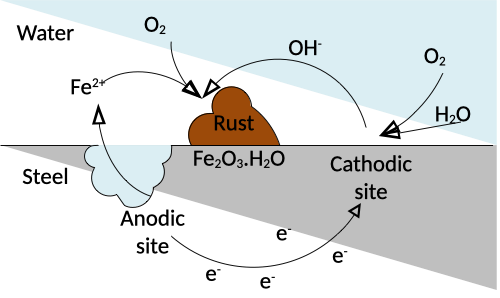
Figure 1: Corrosion process determined by electron flow
As the corrosion process is determined by the flow of electrons, flowing from iron into the electrolyte, one could add an external source of electrons and thus current to provide the necessary electrons for the reaction without utilizing the electrons of the iron atoms, such that rust cannot form.
Protection current requirements
The amount of current required to successfully protect the object is depending on multiple parameters. For example:
- Whether the object is located in the ground or in a water environment;
- The salinity of the environment;
- The resistivity of the surrounding environment.
With a known environment, using for example the European norm NEN-EN-ISO 13174 ‘Cathodic protection of harbour installations’ the total amount of current is estimated. These are in the order of 20 - 100 mA/m2.
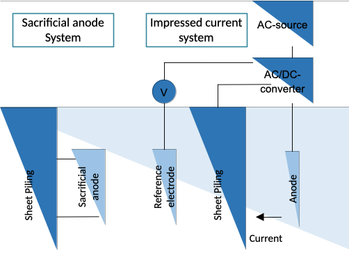
Figure 2: Cathodic protection systems for sheet piling
Sacrificial anode systems
When two different metals are connected and placed in the same electrolyte a galvanic cell is produced. The more electro-negative metal behaves like an anode and oxidizes in a closed circuit while releasing electrons. The open circuit driving voltage between the anode and the to be protected object creates a polarizing current at which the object behaves like a cathode with the idea that the cathode does not corrode.
Design of sacrificial anode systems
With the required current known a type of sacrificial anode needs to be chosen. This is done based on the geometry and available space of the structure. With a chosen anode the electrical resistance between the anode and cathode can be computed, after which the current output of a single anode is determined as follows (NEN-EN-ISO 13174):
$R_a = \frac{\rho}{2AL}(ln(\frac{4L}{r}) - 1)$
Where $R_a$ is the anode resistance, $\rho$ the resistivity of the electrolyte, $A$ the exposed anode area, $L$ and $r$ the length and radius of the anode respectively.
When computing the output current of an anode the resistivity changes over time need to be taken into account. Over time the anode will corrode, releasing ions into the electrolyte and reducing the weight and changing the geometry of the anode, resulting in different resistances and output currents over time. With the current output known at both the beginning and end of lifetime the average output current and the total required amount of anodes can be computed and the lifetime of the total system can be determined.
Impressed current systems
Instead of using sacrificial anode systems a driving voltage between the steel structure and an electrode can be obtained by using an external electrical power source. In that case the electrons required to minimize the corrosion process are obtained from a DC-voltage source. The main advantage of impressed current systems is that a feedback loop can be created which controls the driving voltage based on the amount of protection required. With impressed current systems there is higher control of the achieved protection level. However this comes at the cost of higher maintenance in sometimes difficult to reach locations.
Design of impressed current systems
Using an impressed current system often less electrodes are required than sacrificial anodes. Still electrodes are placed in near proximity of each other, resulting in mutual influences with respect to the total resistance between an electrode and the steel structure.
There is also a finite ability to control the driving voltage of the different electrodes. Often a rectifier is used to control multiple electrodes, meaning that multiple electrodes are driven at the same driving voltage. Electrode distances should be designed such that all electrode-circuits contain approximately the same amount of total resistance to achieve the same current outputs for each electrode. This often results in thicker cables for longer electrodes.
Impressed current vs sacrificial anodes
It is not always straight forward which type of cathodic protection is the best in a certain situation. From an ecological perspective, impressed current systems require constant power, while sacrificial anodes are solving metal ions into the surrounding water. It is always a trade-off and the design must be carefully chosen.
Other restrictions sometimes simplify the choice between the different types of protection. For example in sweet water sacrificial anode systems lose their driving voltage capabilities and therefore lose the ability for cathodic protection. At the same time in harbour installations it might be impractical to use impressed current systems as these require more space from the dock, making it difficult for ships to dock at locations with impressed current systems.
Conclusion
Witteveen+Bos, in collaboration with the parties involved, advises on and designs Catothodic Protection systems. The goal is to work together on a safe environment, while minimizing the ecological effects of both corrosion as well as the byproducts of cathodic protection.