Overhead Systems for Trains
In the period from 1850 - 1900, trains were already travelling the world. Steam trains, to be exact. Diesel engines did not yet exist. What was emerging, however, was electricity. The Icons of EE series describe the pioneers and their differences of opinion throughout the Current War. Railway operators in Europe also did not agree on what the best overhead voltage was for their electrically powered trains. To save on coal and manpower, transport companies tried to run their trains electrically. But how? What kind of electric motors are you going to use? And what kind of voltage are you going to put on the overhead wire?
This article is brought to you by Ricardo Rail, a leading technical consultancy firm in the railway sector. Read more about Ricardo Rail at the end of this article.
The role of traction motors
In the past, power electronics were not yet available. The train’s motors were therefore more or less offered directly to the motor. As a result, 3-phase AC motors were virtually unsuitable: after all, you would need multiple overhead wires over the same track. Moreover, trains run at a variable speed. Sometimes they travel fast, but they also sometimes have to stop at stations. This means that three-phase motors are not really suitable: if you feed them a fixed frequency, they prefer to run at a fixed speed. And means of converting a fixed frequency into a variable one did not exist at that time: that technology only came up around the 1980s - 1990s. Therefore, only one type of motor was common: the DC motor. This could also be designed as a series motor; where the field and armature windings are in series so that (with some minor adjustments) it could also be powered by AC voltage. An additional advantage is that the torque delivered is much more constant over the speed range (at a given voltage/frequency) than with other motors. A major disadvantage, however, is maintenance: DC motors use brushes and collectors. These can wear out and become dirty, causing severe arcing. They therefore require regular maintenance. Modern trains are therefore switching to three-phase motors, which can be powered by modern power electronics An additional factor is that it is difficult to build motors for high voltage, especially motors with carbon brushes and a collector. Series motors of the time could therefore be powered by a voltage of no more than about 750 volts. This had to be taken into account when choosing a power system.
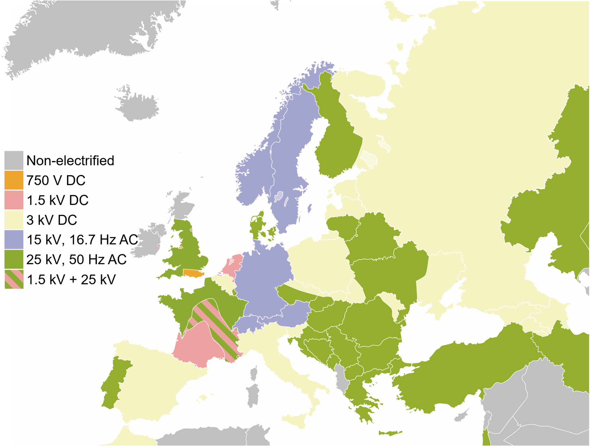
Figure 1: Overhead power systems in Europe
The different power systems
If you’ve ever looked at railroad networks across borders, it won’t surprise you: all over the world, different choices were made. But why, exactly? What are the trade-offs? Figure 1 shows the voltages used in Europe. There are three options: relatively low DC voltage (1.5 - 3 kV), higher AC voltage with low frequency (16.7 Hz) and AC voltage with grid frequency (50 Hz). Why exactly these options?
1. DC
The simplest method would be a direct voltage of 700 - 750 volts. You can offer this voltage directly to the series motor. This voltage is therefore widely used in trams and subways. For main railroads a voltage of 750 V is a bit on the low side. The transport losses are simply too high. Therefore, sometimes 1500 V is chosen. To keep the voltage low enough for the motor, at least two motors are always connected in series. A great additional advantage is that it is the highest voltage at which, before the occupational health and safety rules existed, it was possible to work on a wooden ladder on the overhead line while it was energized! Nowadays, that is unimaginable. To control power and speed, a combination of series/parallel switches and series resistors were used:
- When moving off, the motors are in series, plus series resistors.
- Then slowly series resistors are short-circuited.
- When the current gets too low again, the motor groups come in parallel. First with resistances in series, which are again slowly shorted.
- When the maximum speed is reached, another field weakening resistor is added in parallel with the field winding. This decreases the field current, and thus the ‘back-EMF’ across the armature, again increasing the armature current.
In other countries like Belgium, 3 kV was chosen. You couldn’t do any maintaining when under voltage. Nowadays that is no longer allowed anyway, and the higher voltage has a big advantage: your transport loss is four times lower!
2. Low-frequency alternating current
AC voltage has the great advantage that you can transform it. Thus, a high voltage can be used, which is transformed downwards in the train with an on-board transformer. However, such a transformer is a clunky thing weighing several tons, especially at low frequencies. This adds weight to the train, but the big advantage is that the transport losses are much smaller over long distances. This was therefore widely chosen in larger countries such as Germany. Another additional advantage of AC voltage is that no series resistors are needed: the voltage can be regulated by using a tap changer on the transformer. This saves even more energy. But why was this different frequency chosen in the first place? Like 16⅔ Hz in Germany, or 25 Hz in the United States, for example? There were a few considerations:
- The higher the frequency, the more compact transformers become. So you can transport power with less cost.
- The lower the frequency, the better electric motors of the time worked.
For the public grid, a compromise was found at 50 Hz (Europe) or 60 Hz (USA). However, railroads used the energy mainly for electric motors, so the trade-off was different than on the public grid. There, the compromise was found at a lower frequency. As an additional consideration, the frequency had to be a fraction of the grid frequency: that way, the generator could possibly be driven by the same shaft as the one for the grid. Once you have chosen that reduced frequency, of course you always have to generate or transport it yourself. The Deutsche Bahn has its own, single-phase, transmission grid for that purpose. This is mainly fed by specially dedicated generators in existing power plants. In addition, rotating or nowadays also static inverters are sometimes used to feed the railroad network from the public grid. In Norway, for example, there are only static inverters.
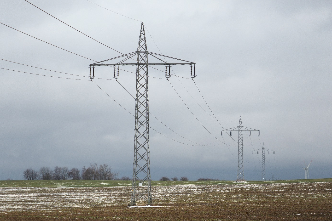
Figure 1: Single-phase railroad transmission grid in Germany. Do you notice that there are two conductors hanging together at both ends, instead of three as is common in the public power grid?
Also interesting is that there was a transition between 16 2/3 Hz and 16.7 Hz. This is not simply the same with a different label. In fact, sometimes the grid was powered by a motor generator; a synchronous machine on the public grid coupled with a doubly-fed induction machine (DFIM) on the rail network. Those grids were not synchronized. An inverter just had to apply the difference frequency on the rotor of the DFIM. Since that difference frequency was very small, smaller than the thermal time constant of the motor windings and the inverter, they were exposed to a lot of thermal cycles. To slightly increase that difference frequency without compromising train compatibility, the rail frequency was slightly increased to 16.7 Hz.
3. AC voltage at mains frequency
After the 1960s, semiconductors came in the scene. Using power diodes, alternating current could be converted to direct current, which could be fed to the engines. Now, all of a sudden, the frequency of the AC voltage no longer mattered! Because a completely separate power grid would be costly, railroads could now be powered from the public grid (50/60 Hz). This is therefore the most popular choice for newly electrified railroad systems. It combines the low transmission losses of high voltage with the relative ease of feeding from the public grid.
The choice of overhead voltage in the Netherlands.
The first railroad line to be electrified in the Netherlands was the “Hofpleinlijn”, already in 1908, which today is metro line E between The Hague and Rotterdam. A low-frequency alternating current was chosen: 10 kV, 25 Hz. This was generated with its own power station. The next electrification took place in 1927: the ”Oude Lijn” (Amsterdam - Haarlem - The Hague - Rotterdam). This time 1500 V= was chosen: the NS found that the weight of the AC traction motors and transformer outweighed the higher transport losses. In addition, this allowed the track to be powered from the public network, with mercury vapor rectifiers. These glass octopuses filled with liquid mercury worked much better on the stable grid voltage and on stable ground than in the train itself. Soon after, in the 1930s, quite a few more lines followed, after which in the 1950s the rest of the Intercity network was completely electrified with 1500 V=. The Netherlands was one of the first countries in Europe to completely abandon the steam locomotive in favor of electric trains and diesel trainsets on its regional railroads.
Future
You may wonder: with the possibilities of today, why don’t we convert everything to ~25 kV 50 Hz? Good question! It would be ideal if we had the same power system everywhere in Europe. Unfortunately, however, the conversion turns out to be hugely invasive. In the Netherlands, for example, it would mean that all reinforcement in concrete structures around the tracks would have to be earthed. However, it is almost impossible to electrically connect all reinforcement in a concrete construction afterwards. Can you imagine that the benefits would soon outweigh this enormous cost? Because 25kV~ proved to be a bridge too far, the Netherlands is now thinking about 3kV=. Then we would at least have the same system as Belgium, Italy and Poland, with a lower energy loss. The overhead wires are already largely suitable for this. Unfortunately this still requires a lot of work: all trains must be converted.
The role of Ricardo Rail
The decisions for the electrification systems have been made a long time ago. However, those decisions in the early 1900s still influence the day to day operations of the railways and the design of trains. Ricardo Rail is active to help operators and manufacturers whenever needed. As one example, we have investigated what the switch from 1,5 kVDC to 3 kVDC can bring to the Dutch Railways in terms of energy usage and performance. As another example: Ricardo Rail performs tests to admit new trains to various national railway networks. One of the requirements is that the current that the train pulls from the overhead wire is free of frequency components that can influence the safety systems in the tracks. The electrification system has a large contribution to those currents: DC systems have strong voltage harmonics of 300 Hz, from the rectification of the three-phase 50 Hz mains, while AC systems mainly have odd line frequency (16,7 or 50 Hz) harmonics. Therefore, to effectively combat issues we encounter, our knowledge about the electrification system is used in day-to-day problems by the Electrical Engineers of Ricardo Rail.
Are you passionate about this technical side of railways? Do you want to be involved in solving complex technical problems in the railway sector? Ricardo Rail is a very non-hierarchical organization with an open-minded culture. Ricardo’s youth association, “Young Ricardo”, may even remind you of the study association you’re currently at! They regularly organize drinks, events and journeys. Ricardo allows for flexible schedules, where one can choose between the office and working from home. Often, office jobs can be alternated with work on the trains. Do you want to know more? Learn more about the job opportunities at werkenbijricardorail.nl!