N-path filters and the future of radios
The astounding evolution of wireless communication started back in 1865 [1], when the scientist James C. Maxwell (figure 1) predicted that electric and magnetic fields propagate through space as waves.
Figure 1: James C. Maxwell.
After Heinrich Hertz experimentally confirmed these expectations, novel applications quickly started making use of this newly discovered world of possibilities. It began with analog wave modulation techniques in the first half of the 19th century and progressed into the use of digital modulation techniques for efficient transfer of information in the current modern era. Today, roughly 67% of the world’s population is estimated to have a subscription to cellular services [2]. Not only is this share growing rapidly, also the number of connected devices per capita is increasing steadily.
Today, roughly 67% of the world’s population is estimated to have a subscription to cellular services.
The advancements in radio evolution have been made possible by the benefits the integration of them into Complementary Metal-Oxide Semiconductor (CMOS) technology offered, such as the low static power consumption, small footprint and low propagation delays. With the discovery of the Metal-Oxide Semiconductor Field-Effect Transistor (MOSFET), Atalla and Kahng [3] laid the groundwork for the discovery of CMOS technology in 1963 [4].
The need for a software radio
To accommodate the huge demand for effective wireless communications, different standards have been developed and many of us use famous examples such as Bluetooth, Wi-Fi, LTE and soon also 5G, on a daily basis. All of these are ideally operated by a single radio integrated in CMOS, which poses to be challenging due to the widely varying standards’ technical details, such as the used frequency bands and bandwidths.
The need for a flexible and efficient radio capable of serving all of these standards, resulted in the introduction of the concept of the software-radio by Mitola in the 90s [5]. It enables access to them by reconfiguring the radio through software only, refer to Figure 2. The scaling of CMOS especially benefitted digital processing capabilities which makes the use of the software-radio extra appealing.
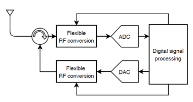
Figure 2: The software-radio devised by Mitola in the 90s.
Ideally, the received spectrum at the antenna is directly converted to the digital domain for further flexible and efficient processing. However, a quick back-of-the-envelope calculation reveals the massive impact this has on the required analog-to-digital converter power consumption. If we take some typical values (bandwidth equal to full sub-6 GHz spectrum, 20 bit resolution to cover large interferers and small wanted signals simultaneously and a Figure-of-Merit of 1 pJ/conversion) then:
PADC ≈ FoM * 2N * 2BW
which evaluates to more than 10 kW!
To limit the required power in the analog-to-digital conversion, we need to add selectivity to the receiver. Traditionally, this is accomplished by a combination of filtering and amplification in the analog domain. Especially the first electromechanical filter offers significant selectivity with minimal losses, noise and distortion, but this type of filters is not flexible and hence not compatible with the heavy increase of required frequency bands in future receivers. Therefore, alternative CMOS- and scaling-friendly techniques for selectivity improvement are being researched.
This research can roughly be classified in 4 categories [6]:
- Feedforward architectures
- Feedback architectures
- Current-mode receivers
- Mixer-first receivers and N-path filters
Feedforward architectures make use of an additional path for out-of-band content. The transfer of this path is subtracted from the main signal path, yielding partial cancellation of unwanted signals. It is difficult to realize an accurate match between both paths, limiting selectivity. The second category makes use of feedback and due to the closed loop configuration, the matching between both paths is less strict, but a larger bandwidth is required in the loop. Current-mode receivers avoid the use of large voltage swings through the use of a Low Noise Transconductance Amplifier up front and the subsequent use of current-mixers and a TIA with virtual ground in which the challenge is to realize the LNTA with sufficient linearity.
N-path filters
The final category is a very promising alternative to traditional electromechanical filters and a widely researched subject, also by our Integrated Circuit Design group [7]–[13]. Mixer-first receivers and N-path filters operate based on the same principle: the impedance transparency of hard-switched mixers allows for upconversion of the low-pass filtering behavior of a baseband capacitor together with the antenna’s 50Ω to an RF-bandpass filter. Figure 3 illustrates this concept.
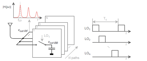
Figure 3: Mixer-first receiver concept.
Intuitively, one can say that the baseband capacitors charge very slowly to the average value offered to them every time their respective LO-switch closes. In-band, this average is equal to the average of a subsection of the incoming sine-wave while this average is close to zero out-of-band, refer to Figure 4.
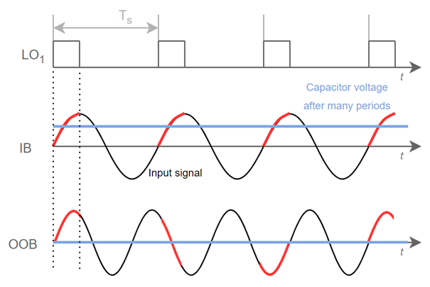
Figure 4: Capacitor voltage in an N-path filter as a response to in-band (IB) and out-of-band (OOB) signals.
We can analyze the transfer function of a mixer-first receiver as depicted in Figure 3 using adjoint network theory [14]. Figure 5 shows the RF-in to RF-out transfer function (vout-RF) in figure 3).
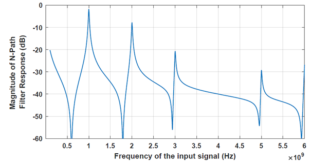
Figure 5: RF in to RF out transfer function of an N-path filter with fLO=1 GHz.
Note how the filter not only passes signals located around the LO fundamental, but also around its harmonics due to the hard-switched nature of the mixers. While Figure 5 clearly shows the desired bandpass filter behavior of this structure, a zoomed plot on the fundamental component of the LO-signal reveals that the selectivity of this filter is rather limited, refer to Figure 6.
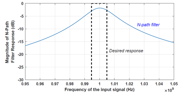
Figure 6: Zoomed plot around fLO of Figure 5.
Figure 6 reveals one of the several downsides related to the use of N-path filters as an alternative to electromechanical filters; the relatively weak selectivity. Other downsides include the harmonic aliasing and the lack of reverse isolation to the antenna (so susceptibility to LO leakage). IC-research over the past decade has intensively focused on alleviating these downsides, because the potential for these filters is huge. The inherently passive nature of N-path filters implies that these structures can achieve excellent linearity. In addition, as only switches and capacitors are used, there is good compatibility with future CMOS scaling, also of the supply voltage. These advantages make N-path filters very appealing for use in future radios. Many ideas for selectivity improvement have already been offered [7], [15], [16]. Now, let’s get to work to solve the rest of its downsides.
References:
[1] J. C. Maxwell, “VIII. A dynamical theory of the electromagnetic field,” Philos. Trans. R. Soc. Lond., vol. 155, pp. 459–512, Dec. 1865, doi: 10.1098/rstl.1865.0008.
[2] Cisco, “Cisco Annual Internet Report (2018–2023) White Paper.” Cisco, Mar. 09, 2020, Accessed: Oct. 27, 2020. [Online]. Available: https://www.cisco.com/c/en/us/solutions/collateral/executive-perspectives/annual-internet-report/white-paper-c11-741490.pdf.
[3] M. M. Atalla, “Semiconductor devices having dielectric coatings,” US3206670A, Sep. 19, 1960.
[4] F. Wanlass and C. Sah, “Nanowatt logic using field-effect metal-oxide semiconductor triodes,” in 1963 IEEE International Solid-State Circuits Conference. Digest of Technical Papers, Philadelphia, PA, USA, 1963, vol. VI, pp. 32–33, doi: 10.1109/ISSCC.1963.1157450.
[5] J. Mitola, “The software radio architecture,” IEEE Commun. Mag., vol. 33, no. 5, pp. 26–38, May 1995, doi: 10.1109/35.393001.
[6] A. Rasekh and M. S. Bakhtiar, “Wide-Band RF Front End for SAW-Less Receivers Employing Active Feedback and Far Out-of-Band Blocker Rejection Circuit,” IEEE J. Solid-State Circuits, vol. 54, no. 6, pp. 1528–1540, Jun. 2019, doi: 10.1109/JSSC.2019.2894996.
[7] M. Darvishi, R. van der Zee, E. A. M. Klumperink, and B. Nauta, “Widely Tunable 4th Order Switched G$_m$-C Band-Pass Filter Based on N-Path Filters,” IEEE J. Solid-State Circuits, vol. 47, no. 12, pp. 3105–3119, Dec. 2012, doi: 10.1109/JSSC.2012.2225542.
[8] M. Darvishi, R. van der Zee, and B. Nauta, “Design of Active N-Path Filters,” IEEE J. Solid-State Circuits, vol. 48, no. 12, pp. 2962–2976, Dec. 2013, doi: 10.1109/JSSC.2013.2285852.
[9] A. Ghaffari, E. A. M. Klumperink, M. C. M. Soer, and B. Nauta, “Tunable High-Q N-Path Band-Pass Filters: Modeling and Verification,” IEEE J. Solid-State Circuits, vol. 46, no. 5, pp. 998–1010, May 2011, doi: 10.1109/JSSC.2011.2117010.
[10] A. Ghaffari, E. A. M. Klumperink, and B. Nauta, “Tunable N-Path Notch Filters for Blocker Suppression: Modeling and Verification,” IEEE J. Solid-State Circuits, vol. 48, no. 6, pp. 1370–1382, Jun. 2013, doi: 10.1109/JSSC.2013.2252521.
[11] Y. Lien, E. Klumperink, B. Tenbroek, J. Strange, and B. Nauta, “A mixer-first receiver with enhanced selectivity by capacitive positive feedback achieving +39dBm IIP3 and <3dB noise figure for SAW-less LTE Radio,” in 2017 IEEE Radio Frequency Integrated Circuits Symposium (RFIC), Honolulu, HI, USA, Jun. 2017, pp. 280–283, doi: 10.1109/RFIC.2017.7969072.
[12] Y.-C. Lien, E. A. M. Klumperink, B. Tenbroek, J. Strange, and B. Nauta, “High-Linearity Bottom-Plate Mixing Technique With Switch Sharing for $N$ -path Filters/Mixers,” IEEE J. Solid-State Circuits, vol. 54, no. 2, pp. 323–335, Feb. 2019, doi: 10.1109/JSSC.2018.2878812.
[13] V. K. Purushothaman, E. A. M. Klumperink, B. T. Clavera, and B. Nauta, “A Fully Passive RF Front End With 13-dB Gain Exploiting Implicit Capacitive Stacking in a Bottom-Plate N-Path Filter/Mixer,” IEEE J. Solid-State Circuits, vol. 55, no. 5, pp. 1139–1150, May 2020, doi: 10.1109/JSSC.2019.2959489.
[14] S. Pavan and E. Klumperink, “Simplified Unified Analysis of Switched-RC Passive Mixers, Samplers, and $N$ -Path Filters Using the Adjoint Network,” IEEE Trans. Circuits Syst. Regul. Pap., vol. 64, no. 10, pp. 2714–2725, Oct. 2017, doi: 10.1109/TCSI.2017.2703579.
[15] S. Krishnamurthy and A. M. Niknejad, “Design and Analysis of Enhanced Mixer-First Receivers Achieving 40-dB/decade RF Selectivity,” IEEE J. Solid-State Circuits, vol. 55, no. 5, pp. 1165–1176, May 2020, doi: 10.1109/JSSC.2019.2956887.
[16] G. Pini, D. Manstretta, and R. Castello, “Analysis and Design of a 260-MHz RF Bandwidth +22-dBm OOB-IIP3 Mixer-First Receiver With Third-Order Current-Mode Filtering TIA,” IEEE J. Solid-State Circuits, vol. 55, no. 7, pp. 1819–1829, Jul. 2020, doi: 10.1109/JSSC.2020.2987715.
 This work is licensed under a Creative Commons Attribution-NonCommercial-ShareAlike 4.0 International License.