The birth of a Segway
The module Systems and Control in the Electrical Engineering Bachelor has always been a painful point and a difficult hurdle for many students. Even before TEM, the course ‘Dynamische Systemen’ was difficult and saw many resitters. With the introduction of this new educational model, more emphasis was placed on an all-encompassing project to tie together all other courses. For the last five years, the goal of this project was to model and control a miniature segway. In the essence, this project is perfect for integrating the knowledge of the different courses: Engineering System Dynamics provides the tools to model the segway using bondgraphs and using Control Engineering a robust controller can be designed to stabilise the segway. All of which is supported by the mathematics on Linear Systems which was also included in this module in previous years. In reality however, there are many challenges to overcome during the limited project time and results were limited due to failing hardware. Nevertheless, the project-and the module in general-has undergone an amazing transformation during these 5 years, and much has improved. This metamorphosis will be unravelled using the help and stories from Mickey Derks, who stood at the cradle 5 years ago.
Before the segway project there was a project where groups of 4-6 students build and controlled hovercrafts around a track. With this project, the controller did not have to be as good, as long as the build quality of the hovercraft was reasonable. Mickey: “Most students considered this project a competition to see who could build the best hovercraft. Usually there would only be a 1 student in each group that quickly bodged together a controller.” Most groups quickly discovered that the controller could still be improved on the spot, by tugging the power cables to nudge the hovercraft in the right direction. Since the focus on this project was not directly on all of the different subjects, the project was revised.
The Birth of an Idea
The concept of a segway at the heart of the new project was conceived with the help of Stefano Stramigioli and the students that had helped with the tutorials organised by Scintilla for the ESD course. “The initial idea was rather simple; a mechanical system is fun because it shows you what you are doing and if it is correct. And the segway is inherently unstable so there is always a control challenge” Mickey says. “The segways are loosely based on the Segways the professors zip around on, because these machines are a great display of what Electrical Engineering is all about”. From very early on, the line sensor was a prominent feature, even though it goes largely unused during the project. But there was more brainstorming to determine what the segway should come equipped with. Initial ideas included a second pendulum on top of the segway and a ‘black box’ with inside a rolling mass, to make the project a bit more complex. As we know now, these did not make the final cut, and neither are they necessary to obtain the right complexity.
The technical brainstorming started early September 2016, about 3 months before the segways were needed for the project. A few features were essential; the system should be able to work with uploadable sketches and to avoid students waddling around with strands of cables (and perhaps tugging them a little), the segway needed to have a battery and a wireless connection. The body should thus be able to contain at least these two functions, which could be realised with a Raspberry Pi and a battery pack, and obviously two motors to drive it. Many people are surprised by the rather small size as they are hoping for full-size Segways, but this small form-factor can easily house the different components. Moreover, Mickey mentions that making them any larger also makes them more dangerous.
If I had to guess I have spent around 1200 hours on developing the segway project.
—Mickey Derks
This general idea was further developed by a number of other students. All under the supervision of a PhD candidate. Since it was already September and the project had to be ready in December, the PhD candidate found students that could quickly develop electrical systems and (perhaps not) coincidentally, many of the students helping out had worked in the Greenteam in the years before. Nevertheless, designing and building 25 segways takes a considerable amount of time. This time pressure was the motivator behind some design choices. Take for instance the segway body, it is constructed of laser cut Delrin, since that material was widely available in the RAM-lab and the technicians had experience with using that material. All circuitry was created on PCBs and contains many components. For large circuits, these are commonly fabricated using automated pick-and-place machines to eliminate all the manual work with the tiny SMD-components. However, placing such an order and having it processed takes time and that was not available. This meant resorting to manual labour and the best way to speed that up is by working together with many people, which is why a PCB population session was hosted with 14 people. Who helped? “Basically everyone we knew that was willing to help that day” according to Mickey. Using a Matlab script of his own devising, a template could be printed to indicate what component went where. This being a rush job and many people helping out meant that performance was sub-optimal, but in the end 15 out of 25 PCBs worked.
Still, the segways could not be fully assembled as vital components were missing. Each segway has two motors and even though the entire project had a large budget, getting motors with a good torque rating from Maxon Motor in this small form was not feasible. Instead, the motors were sourced from China. Once again, time was of the essence and the motors had to get to the Netherlands before the project started, which eliminated all the cheap but slow shipping options. To speed up the shipping process, the idea of travelling to China, collecting the motors, and bringing them back as luggage was quickly discussed. Fortunately, the express shipping option was not that expensive. Nevertheless, getting the 50 motors from Shenzhen to Enschede cost about €300, excluding the Diesel fuel for the car that drove the parcel from Schiphol airport to the campus right after it was unloaded from the plane. Even though the motors arrived in time, some sessions were required to make improvements, since the axles did not have any means of attaching the wheels as there was no thread on the end. The solution to fix this required a number of prototypes. For the first attempt a piece of threaded rod was thermally crimped on the motor axle, but after the second try the motor broke under the heat. The second solution was gluing the threaded rod to the axle and mounting the wheel to that, an easy bodge fix. Except that the superglue melted if students stalled the motor for too long making it overheat, resulting in the axle falling off. The final solution uses metal-epoxy, which does not melt with the heat generated in the motor. This bodge fix also explains why some of the axles are so wobbly, which has not improved by students dropping the segways on the floor. In the end the motors, including adjustments, were ready in time for the motor measurement practical two days before the Christmas break.
The first motor measurements were not very successful, it is easy to blame the hardware, but the limiting factor was the lack of structure for the measurements. On top of the limited capabilities of the 20-Sim 4C software. The software ran on the student’s laptop, which at the time were the poor performing Dell models which had difficulties connecting to the segway using a Wi-Fi connection. Dropping just one packet was sufficient to break the controller. Controllab, the developer of the 20-Sim software, did not think it was even possible to control something using a Wi-Fi connection, because the 20-Sim 4C software was only designed to work with an ethernet cable.
Many students had no clue on where to start modelling a motor, let alone what measurements to perform to determine the motor parameters. Back then, the segways were still equipped with a strain gauge measurement set-up, which had only been added three hours before the project session, while the drivers for it were only completed five hours before the session. Mind you, the session started at 8:45 in the morning! Nevertheless, connecting to the segway and uploading a sketch was difficult. Since most of the student assistants had been busy with building the segways in the first place, there had not been much time to write manuals or instructions. So, it was a tough time getting around 20-Sim 4C and getting the segways to do anything.
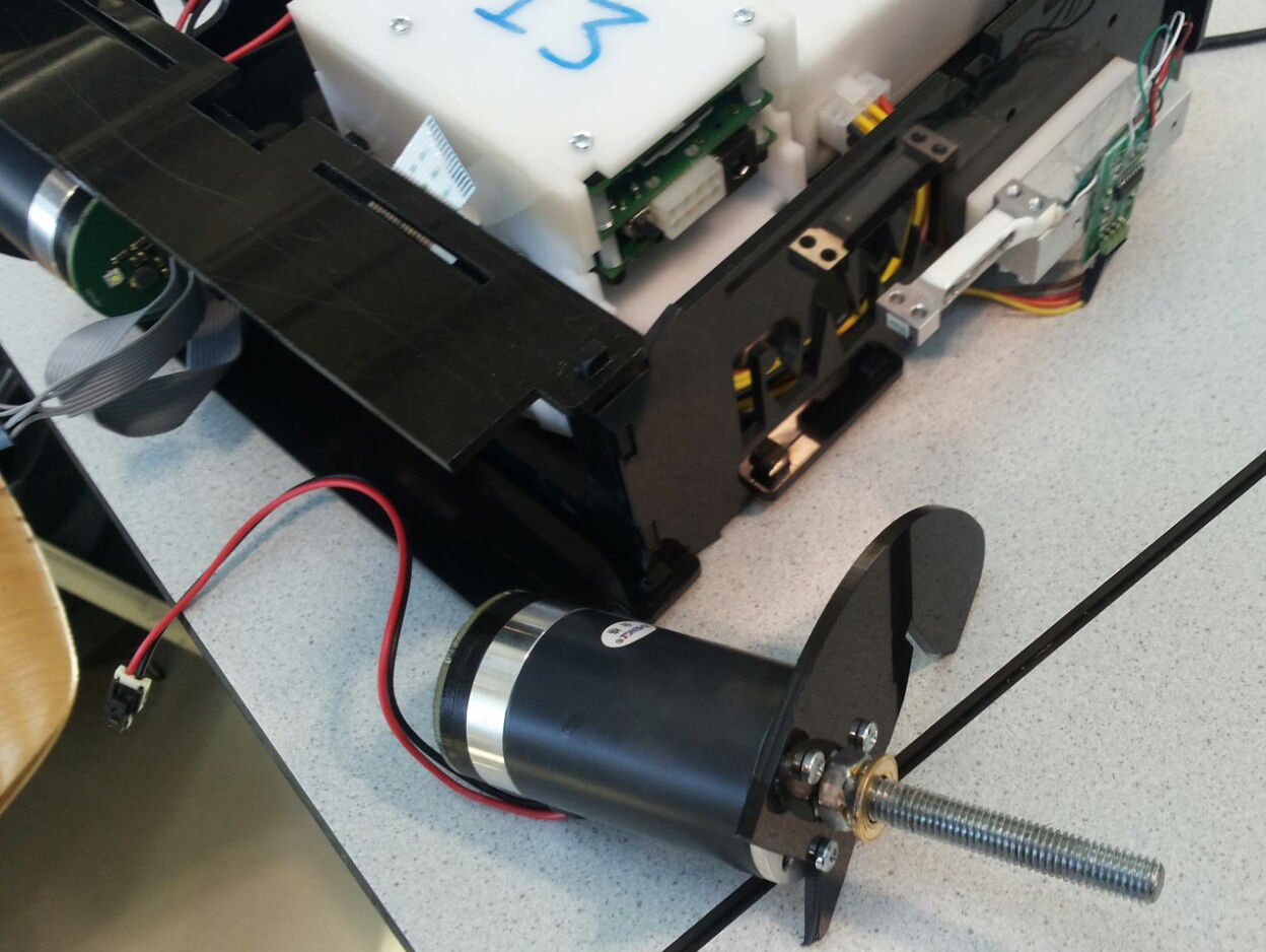
Figure 1: A segway with the strain gauge attached, but one axle broken off.
After the holiday break there was opportunity for the students to redeem themselves in the actual project. Still there were many issues with the software. Fortunately, the project was held in the DesignLab, right next to the Gallery. So, in the case of obscure 20-Sim errors, the student assistants could always refer to the Controllab’s office a few doors down. At this points many students had attempted connecting to segways and attempted to perform some measurements, but the segways were treated poorly in the process. Some segways had taken an unvoluntary plunge from a table as the motors were spinning violently, and some parts of the body had already broken off (see figure 1). With 20 working segways and perhaps some spares this would not have been a problem, but at this point there were only 5 segways that were not entirely broken. By the end of the project, when the handful of working controllers were to be demonstrated, there was only 1 working segway remaining. There were a handful of groups that managed to design a working controller, that could not manage more than balancing the segway on the spot.
Motor drivers
After poor performance in the first year, the segways were more or less discarded and completely new versions were built. The first generation were equipped with the VNH2SP30-E motor drivers that were used within the RAM group, so their excellent performance was well established. The downside of these motor drivers was that they had to be mounted on a separate PCB because of the size. Moreover, these chips could only be driven to 16V, lower than the desired 24V and different from what seemed like 41V if you look at the frontpage of the datasheet in a hurry. Which definitely happened since there were only 3 months to complete the entire project, so everything was done in a hurry. In the second design the successor motor driver, the VNH3SP30-E, was tried, as it had the same footprint and pin lay-out and could actually supply 40V. These had another downside however; they had no current sensor. Since these were essential for the controller, this IC didn’t make it onto the segway.
Instead, another motor driver was found; the MC33926PNB from NXP. These have a current sensor and can supply the desired 24V but had a tight margin on the supply voltage. This was no problem under normal operations, however when stopping suddenly, the back-EMF from the motor could generate high voltages that would break this chip. This flaw in the design was only discovered during the project which led to some motor drivers suddenly giving out. This failure was most dangerous because the motor drivers, after breaking down would—instead of becoming an open circuit or a short circuit—become a low ohmic connection allowing a very high current to be drawn from the batteries and dissipating a lot of heat. The battery pack was built with decent quality Panasonic cells that, at ~30A, can deliver serious currents and are normally used to drive power tools, but are also useful for driving the segway’s motors.
A possible solution to solve this problem was to use more capacitance to smooth these voltage spikes, but high capacity and high voltage and thus bulky capacitors did not fit in the housing with the Pi. The final solution was to use a transient voltage suppressor (TVS) which is basically a large Zener diode that can filter the large peaks. These were soldered on top of the existing capacitors to provide additional protection.
More improvements
After the serious flaws with the motor drivers were resolved, the other major problem, the connection issues, were resolved by making the segways connect to Eduroam instead of to a router setup in the lecture hall. This meant a stable connection could be setup and removed the need for setting up routers everywhere. After the major flaws from the year before were fixed, there was some time to work on other features.
The gamepads were an addition to the third edition of the project as a way to make the project more fun for students that could complete the simple challenges. Controlling the segway manually was a logical next idea. This was a ‘nice-to-have’ feature, so it was decided not to spend the project’s budget to buy 30 official Playstation controllers. Instead, cheaper clones were bought. The drawback being that they do not all have the same standards as the official version. After a small batch was ordered and made to connect with the Pi in the segway the remaining gamepads were ordered to have one with every segway, only to discover that these had slightly different chips inside which meant that Mickey had to spend another week and a half to adapt the Bluetooth Driver to these new gamepads.
In the years after more time was spend on making the segways more robust and reliable. On the one hand the firmware was updated. Next to that new efforts were made to finally ensure that there were 30 segways that each had all of the components fully operational. This meant unscrewing all the covers and swapping out the defective hardware with functioning replacements.
This year, another new feature was added to ensure that students can also connect to segways if they are not connected to the Eduroam network. The solution is clever, if the segway is not connected to a network it becomes an access point that you can connect to with a laptop. Using a bespoke tool, it is then possible to configure the segway to connect to your own private Wi-Fi network. This means that you can disconnect from the segway and access the internet and the segway simultaneously.
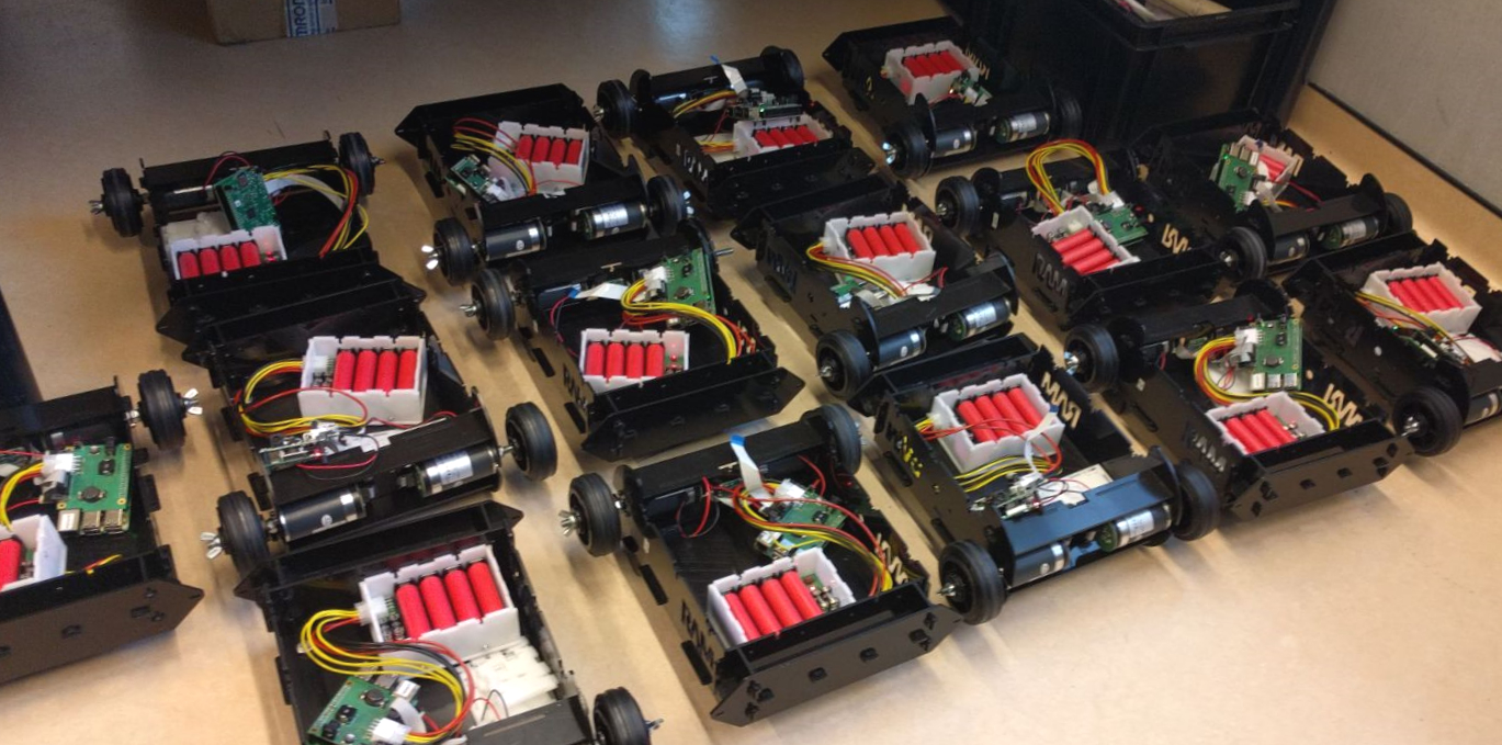
Figure 3: Segways with the battery pack and power shield visible.
What is next?
“Well, the next logical step is to make a redesign of the current segway or improve specific components.”, Mickey says. “On top of that, another ten segways will be built to accommodate the growing number of students attending the module”. According to him there are three major bugs remaining in the segways as they are now. There are ten segways that refuse to charge. Then, some batteries will not charge because the charge level is below the minimum voltage set by the battery management system. “And there is a particularly nasty bug where if the controller designed by the student is too noisy, this noise will transfer over to the measurements from the sensors. This one is particularly difficult to fix or test”, Mickey says.
What is most remarkable is that the project was largely run and developed by students. The teaching staff had little to do with the design and much of the organisation was initially organised by just one PhD candidate. Obviously, this was quite demanding; Mickey’s answer to the question on the hours worked for the module 6 project the last five years: “Well that is a difficult answer, maybe 2000 hours if you include supervising during the project itself, but if I had to guess I have spent around 1200 hours on developing the segway project. With everyone together we might add up to 5000 hours on development alone.”
Even though much more could be improved about the segway, even after more than 5 years of development, it has come a long way and much has improved compared to the first project in 2016. As a student starting the project today it is difficult to comprehend the progression in this project and the hardware within and to compare the quality now to the quality back then instead of to similar projects. It was only in 2020 that the problem was solved where students did not have the required prerequisite knowledge to systematically design a controller that could balance the segway themselves. In the years to come the last of the issues will hopefully be resolved and then the segway project can be the perfect integration project.